Rooms directed toward the water
The Z-shaped massing opens different view angles; the sawtooth frontage turns individual window bays toward the bay and sea horizon.

 Contractor
 Reviewing authority
Architectural design presentation · September 2026
Wafaiya Yanbu Hotel & Annex
A five-star hospitality proposal for the Red Sea coast.
Project / investor identityContractorReviewing authorityThe design
The architecture combines the privacy of a retreat with the public life of a hotel and events destination.
The Z-shaped massing opens different view angles; the sawtooth frontage turns individual window bays toward the bay and sea horizon.
Dining, terraces, pool and wellness extend the guest experience beyond the room.
A distinct entrance and large halls allow event and recreation uses to operate with greater independence from the hotel.
Warm stone, bronze-toned solid aluminium and layered shading connect the exterior to the interior.
The design
A clear relationship between the urban approach, the landscaped arrival and the Red Sea frontage.
The massing opens a sequence from the arrival courts through the hotel to sea-facing dining, balconies and terraces. The annex holds its own arrival address while the bridge expresses a connected destination.
The bay offers foreground activity; the wider sea horizon gives distance and sunset identity. These are distinct view qualities to record from each key.
The design
Context evidence supplied by the design team, shown alongside the presentation visualisations.
The bay defines the principal landscape and guest-experience edge. The building form responds through several frontage orientations.
Read arrivals, annex access and parking against the surrounding streets and public realm.
Use the confirmed survey and true north for views, sun, wind and all future contextual renders.
The design
The Z-shaped building establishes the view opportunities; the sawtooth bay refines the orientation of each room.
The angled face can direct a room’s primary view obliquely toward the bay, where a straight elevation would look more squarely inland or toward a neighbouring wing.
The return wall and side screen can interrupt direct balcony-to-balcony sightlines. Their height, angle and perforation need checking from both seated and standing eye levels.
Rationalise the folds, glazing modules, corner details and screen fixings. The value is stronger views and identity with a controlled number of components.
The design
A clear hierarchy of experiences, supported by a room-by-room view schedule in the next design stage.
The checklist describes 50% of rooms with full bay and sea views, 30% with approximately 75% sea exposure, and 20% with approximately 50% horizon exposure.
For each key, record the bed, seating and balcony views; the floor level; adjacent privacy; potential future obstructions; and glare at the intended use time.
The design
Separate guest, event and service movements while maintaining an understandable relationship between the buildings.
Arrival court, concierge, reception and guest lifts create a legible route to the guestrooms.
The annex lobby provides a separate address. Event visitors can enter without using the main hotel reception sequence.
Basement kitchens, laundry, ramps and service lifts provide the operating backbone. Confirm loading, waste and event set-up routes on a coordinated circulation overlay.
The design
A flexible activity anchor that can support hotel business and destination use throughout the day.
The ground plan tags an indoor sports area of 1,143 m² and an indoor gymnasium of 1,135 m², with a central lobby, toilets, stairs and support rooms.
The project brief proposes multipurpose event use. Exhibitions, receptions and community events can complement sports, subject to approved layouts and operational planning.
Project numbers
Separate the building footprint, the above-ground floor-area reference and the total built-up area.
| Level / basis | Main hotel m² | Annex m² | Combined m² |
|---|---|---|---|
| Basement | 14,159.50 | — | 14,159.50 |
| Ground | 5,568.97 | 3,020.00 | 8,588.97 |
| Mezzanine | 2,471.25 | 805.00 | 3,276.25 |
| First | 3,402.75 | 805.00 | 4,207.75 |
| Second | 3,402.75 | — | 3,402.75 |
| Third | 3,402.75 | — | 3,402.75 |
| Fourth | 3,402.75 | — | 3,402.75 |
| Fifth | 3,402.75 | — | 3,402.75 |
| Sixth | 3,402.75 | — | 3,402.75 |
| Roof floor | 1,700.00 | 1,510.00 | 3,210.00 |
| Above-ground scheduled area | 30,156.73 | 6,140.00 | 36,296.73 |
| BUA incl. basement | 44,316.23 | 6,140.00 | 50,456.23 |
GFA reference: the supplied above-ground floor-area sum, including the stated roof floors: 36,296.73 m².
BUA: all supplied scheduled floors, including basement and stated roof floors: 50,456.23 m².
Footprint: ground-floor area of 8,588.97 m². Hotel coverage is 32.99%; annex coverage is 59.99%.
Project numbers
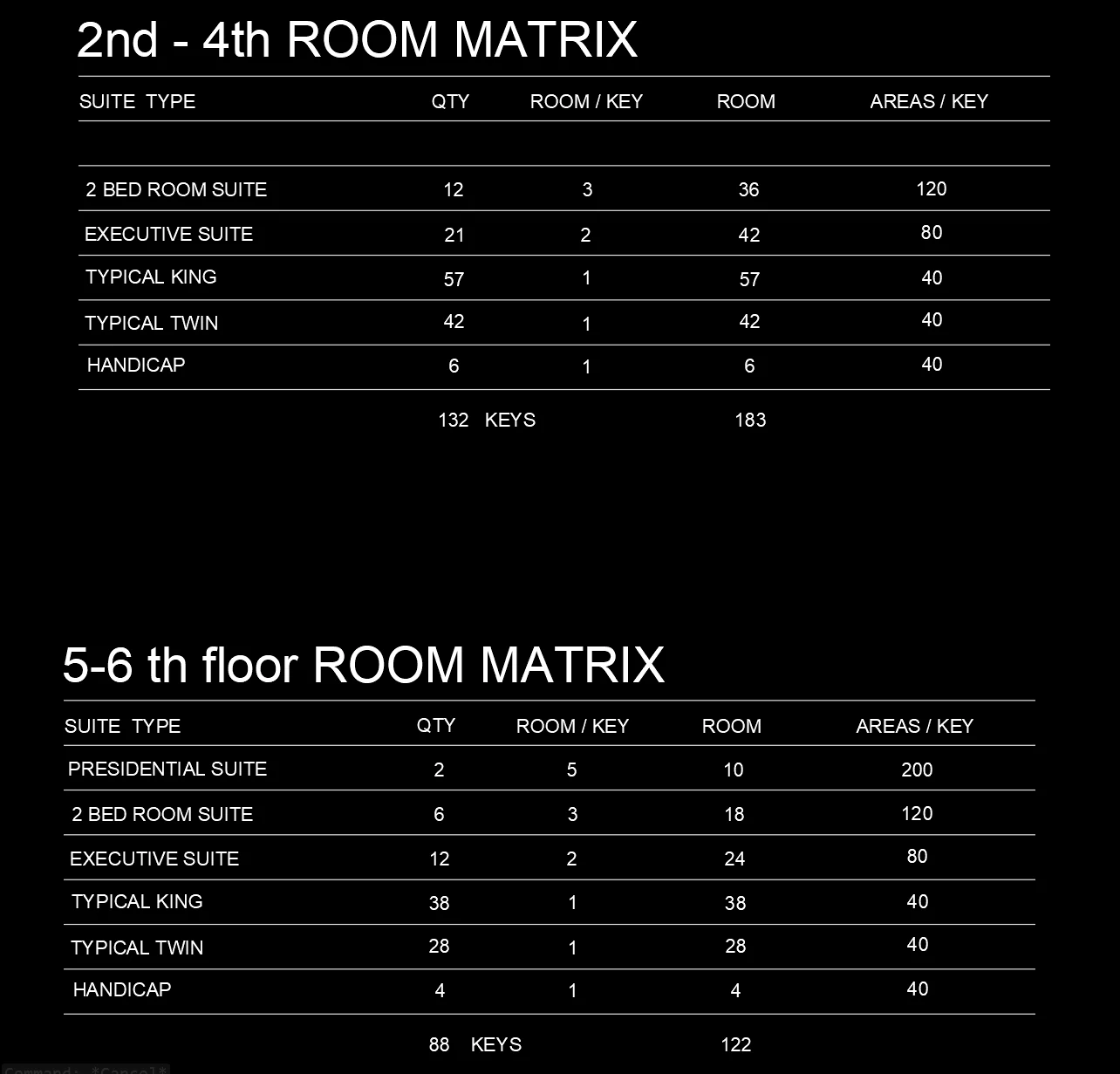
Client-confirmed capacity: 61 modules on each of floors 2–6. The table below shows the separate, provisional sellable-key interpretation.
| Room / key type | Floors 2–4 keys | Floors 5–6 keys | Total keys² | m² / key¹ | Total m²¹ | Key mix² |
|---|---|---|---|---|---|---|
| Presidential suite | 0 | 2 | 2 | 200 | 400 | 0.9% |
| Two-bedroom suite | 12 | 6 | 18 | 120 | 2,160 | 7.9% |
| Executive suite | 21 | 12 | 33 | 80 | 2,640 | 14.5% |
| Typical king | 57 | 38 | 95 | 40 | 3,800 | 41.7% |
| Typical twin | 42 | 28 | 70 | 40 | 2,800 | 30.7% |
| Accessible room | 6 | 4 | 10 | 40 | 400 | 4.4% |
| Total calculated from rows | 138 | 90 | 228 | — | 12,200 | 100% |
The supplied suite mix uses 183 modules on floors 2–4 and 122 modules on floors 5–6: 305 modules in total. Suites combine modules behind one sellable key.
Guest experience
A five-star experience depends on the complete room, from arrival and storage to privacy, sleep quality and outlook.
Warm timber, sand-toned stone, bronze accents and restrained teal connect the guestrooms to the public spaces.
Coordinate side screens, solar-control glazing, blackout curtains and furniture so the view is comfortable at the time guests use it.
Check furniture clearances, accessible routes, luggage, bathrooms, acoustics and air distribution in a coordinated prototype before repetition.
Guest experience
A hierarchy of spaces serves intimate meetings, hotel banquets and larger activities in the annex.
The ground plan tags Hall 1 at 736 m² and Hall 2 at 637 m². Prefunction, buffet/breakout and preparation areas support the event sequence.
Seven multipurpose-room tags, smaller meetings, a conference room, breakouts and a prayer room offer several event scales.
Large annex volumes extend the offer. Coordinate conversion layouts, acoustic separation, AV, rigging, storage and service access for every proposed use.
Guest experience
The hotel’s leisure value comes from the relationship between indoor wellness and the landscaped coast-facing spaces.
The Revit plan includes men’s and women’s gyms, spas, massage rooms, saunas, steam rooms and Moroccan baths.
Provide shaded resting areas and tested wind shelter. Keep the central outlook open while treating exposed returns and corners.
Coordinate wet and dry routes, privacy, changing facilities, drainage, pool servicing and staff access with the operator.
Guest experience
The environmental study identifies the exposed roof as the priority for further design testing.
The roof combines hospitality uses with a strong coastal outlook. Its viability depends on a comfortable outdoor edge, service access and space for the building systems.
Place long-stay seating behind a tested screen line and provide overhead shade with supplementary protection from low western sun.
Reserve plant, maintenance, drainage, PV, access and fire routes before the restaurant and terrace boundaries are fixed.
Climate response
Use wind analysis to place activities and refine the building’s outdoor rooms.
Seventeen wind cases examine the whole rose and individual directions at 1.75 m above selected surfaces. The reported ground-level aggregate contains no “uncomfortable” area, but a substantial share is suited to walking rather than sitting.
Design response: locate longer-stay seating in sheltered zones; test the roof edges, corners, entrances and terrace openings individually. A site-wide percentage does not establish dining comfort at every point.
| Reported case | Scale | Sit / stand | Stroll / walk | Uncomfortable |
|---|---|---|---|---|
| Whole rose, aerial | NEN 8100 | 22% | 77% | 0% |
| Whole rose, plan | NEN 8100 | 21% | 79% | 0% |
| NW 315° | NEN 8100 | 22% | 77% | 0% |
| Whole rose, site | Lawson LDDC | 6% | 93% | 0% |
| Whole rose, oblique | Lawson LDDC | 5% | 95% | 0% |
Climate response
The architectural aim is a comfortable occupied zone with a usable sea outlook.
Test porous or operable screens along exposed edges. Set dining inboard of the parapet, and compare several screen options in the model.
Use planted shelter at exposed returns and upwind ends. Assess the sitting zone rather than relying on a general walking-comfort result.
Screens, planters and shade structures all require wind-load design, secure fixings and maintainable coastal finishes. Planting on slabs is part of the structural coordination.
Climate response
The same solar exposure that creates shading demand also creates an opportunity for integrated generation.
The report quotes approximately 6,246 m² of panels at 60% coverage and 15% efficiency. The selected surface includes model geometry; it is not a confirmed installable roof array.
Reconcile the analysis location, usable roof and canopy areas, plant clearances, structure, maintenance, shading, module data and system losses. Confirm a new annual yield before investment decisions.
Climate response
The supplied frames show how the massing redistributes shade; afternoon use areas need deliberate landscape and facade protection.
Climate response
The facade should vary where orientation and exposure vary, while maintaining one architectural language.
Balconies, canopies and roof pergolas can intercept higher-angle sun. Size them for the actual facade azimuth and occupation hours.
Use the sawtooth returns, vertical fins and adjustable or perforated screens to address low-angle exposure while preserving selected view corridors.
Coordinate glazing, opening area, curtains and internal blinds with energy, daylight and glare models. Compare wing-specific facade options using the same room and HVAC assumptions.
Landscape
A low, coastal planting character reinforces the architecture while framing water, shade and movement.
Use lower planting in primary view corridors and locate taller elements to frame arrivals, edges and sheltered seating.
Coordinate saturated planting loads, root anchorage, soil volumes, waterproofing, root barriers, drainage, overflow and inspection access.
Group plants by irrigation demand and exposure. Test irrigation-water and soil salinity; provide drainage and a maintenance plan.
Landscape
The supplied palette is a strong starting point for Yanbu’s salt exposure, dry conditions and open sea views.
| Plan code | Plant | Presentation role | Coordination requirement |
|---|---|---|---|
| P01 | Arak / miswakSalvadora persica | Primary small-tree candidate | Engineered pockets; confirm canopy, salinity and supply. |
| P02 | Samr / umbrella thornVachellia tortilis | Reserve shade-tree option | Keep thorns away from guest paths; confirm root volume and exposure. |
| P03 | Doum palmHyphaene thebaica | Reserve accent palm | Allow mature crown, weight and anchorage; engineered pockets only. |
| P04 | Coastal saltbushSuaeda vermiculata | Coastal shrub / cover | Use for exposed mineral beds; verify nursery provenance. |
| P05 | Succulent saltbushTetraena coccinea | Low coastal massing | Confirm identity; regional literature also uses Zygophyllum coccineum. |
| P06 | Coastal sea lavenderLimonium axillare | Flowering coastal edge | Trial in the specified substrate and irrigation regime. |
| P07 | Thumam grassPanicum turgidum | Dry, sheltered mineral beds | Keep clear of routes and services; confirm mature spread. |
| P08 | Creeping saltgrassAeluropus lagopoides | Low saline-tolerant cover | Define edges and maintenance; keep drains inspectable. |
| P09 | Silvery groundcoverCressa cretica | Low coastal cover | Useful where long sea sightlines must remain open. |
| P10–P12 | Client reference palm, tree and clipped shrub | Visual references only | Species, native status and mature size remain unconfirmed. |
Materials
The supplied boards connect material character, facade use and coastal durability.
Materials
The supplied boards connect material character, facade use and coastal durability.
Materials
A shared material and pattern vocabulary connects the facade with the public interiors.
Use solid aluminium panels for the selected metal-clad zones, soffits and laser-cut decorative screens. Coordinate panel thickness, stiffeners, joints and replaceable fixings with the facade engineer.
Repeat the bronze tone and selected pattern in lobby screens, feature panels and ceiling accents. If a perforated panel is intended to absorb sound, coordinate the tested acoustic backing and cavity.
Specify verified pretreatment, finish class, fabrication quality and a coastal warranty. Laser-cut and deburr before finishing; protect cut edges and isolate incompatible metals.
Materials
The two masonry leaves provide the enclosure; continuous insulation, controlled air leakage and a drained outer finish complete the performance strategy.
Carry insulation past columns and slab edges. Check balcony connections, metal brackets, window perimeters and roof junctions as thermal bridges.
Provide drained and inspectable interfaces. Select the air/vapour-control strategy from a project-specific condensation assessment for air-conditioned coastal conditions.
Engineer ties, supports, cavity fire barriers and movement joints. Verify acoustic and fire performance of the complete assembly and provide access to replace facade components.
Materials
The presentation connects the design intent with the evidence needed to substantiate it.
| Strategy | Evidence to carry into procurement | Decision basis |
|---|---|---|
| Solid aluminium | Verified recycled content; product EPD where available; finish and sourcing records. | Match the selected LEED version and credit criteria. |
| Stone, porcelain and other finishes | Product-specific environmental information and durable, repairable installation. | Do not infer environmental performance from material name alone. |
| Paints, adhesives, sealants and interiors | VOC content/emissions evidence where required; ingredient disclosures where applicable. | Review wet-applied products and composite assemblies individually. |
| Envelope, roof and glazing | Energy model, assemblies, glazing properties, thermal bridges and commissioning. | Savings need a model and baseline; no percentage is claimed here. |
| Landscape and water | Planting/irrigation schedule, water demand and water-quality data. | Native or regional planting does not by itself prove water savings. |
| PV and operation | Coordinated array, annual yield model, metering and maintenance plan. | Source Forma estimate is preliminary. |
The project brief calls for LEED-compliant material selection. Use a materials register linking every specified product to the relevant evidence and the project’s selected LEED rating system.
Prioritise replaceable panels, maintainable coatings, accessible drainage and robust interfaces. Whole-life value depends on preserving performance under salt, humidity and UV exposure.
Plans & architecture
Programme distribution helps explain the building before the detailed drawings are reviewed.
The public floors form the hotel’s social and event base. Five guest floors share the repeated room-module system. The roof adds a destination venue, while the basement supports the hotel’s daily operation.
The following pages move through every supplied floor plan, then the elevations and sections.
Plans & architecture
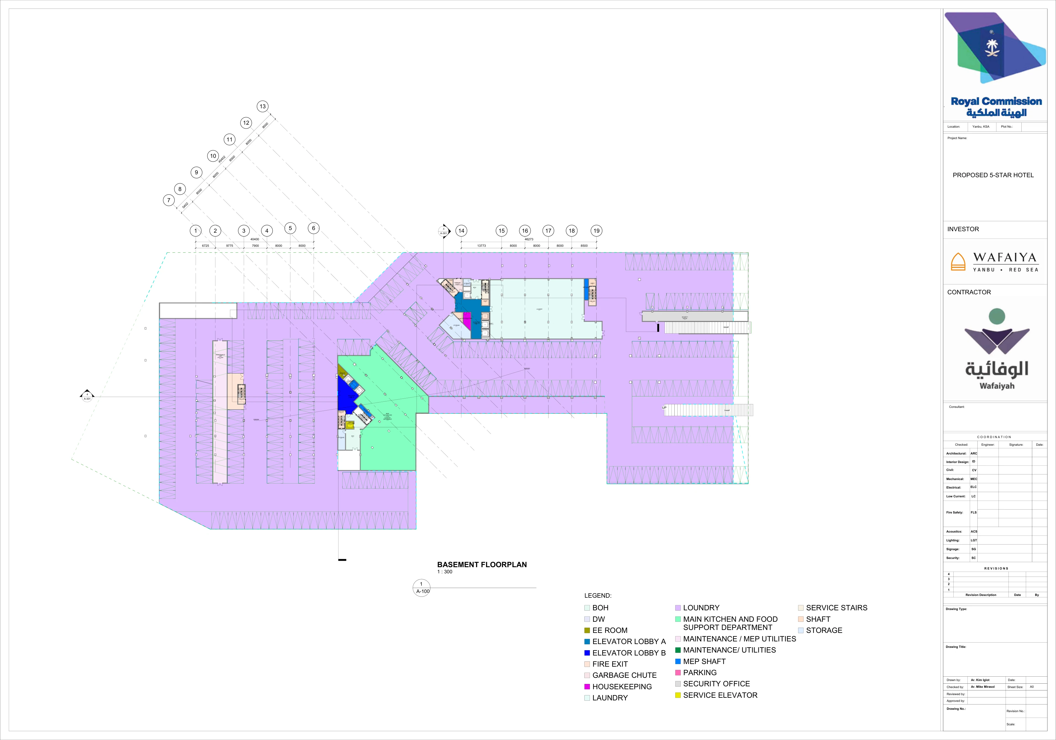
14,159.50 m² scheduled area
Parking, main kitchen and food support (760 m² tag), laundry (688 m²), security (103 m²) and maintenance/MEP (229 m²).
Concentrates support functions beneath the guest-facing programme and links them vertically through service cores.
Verify parking totals, accessible bays, loading/receiving, waste flow, ventilation, compartmentation and ramp geometry.
Plans & architecture
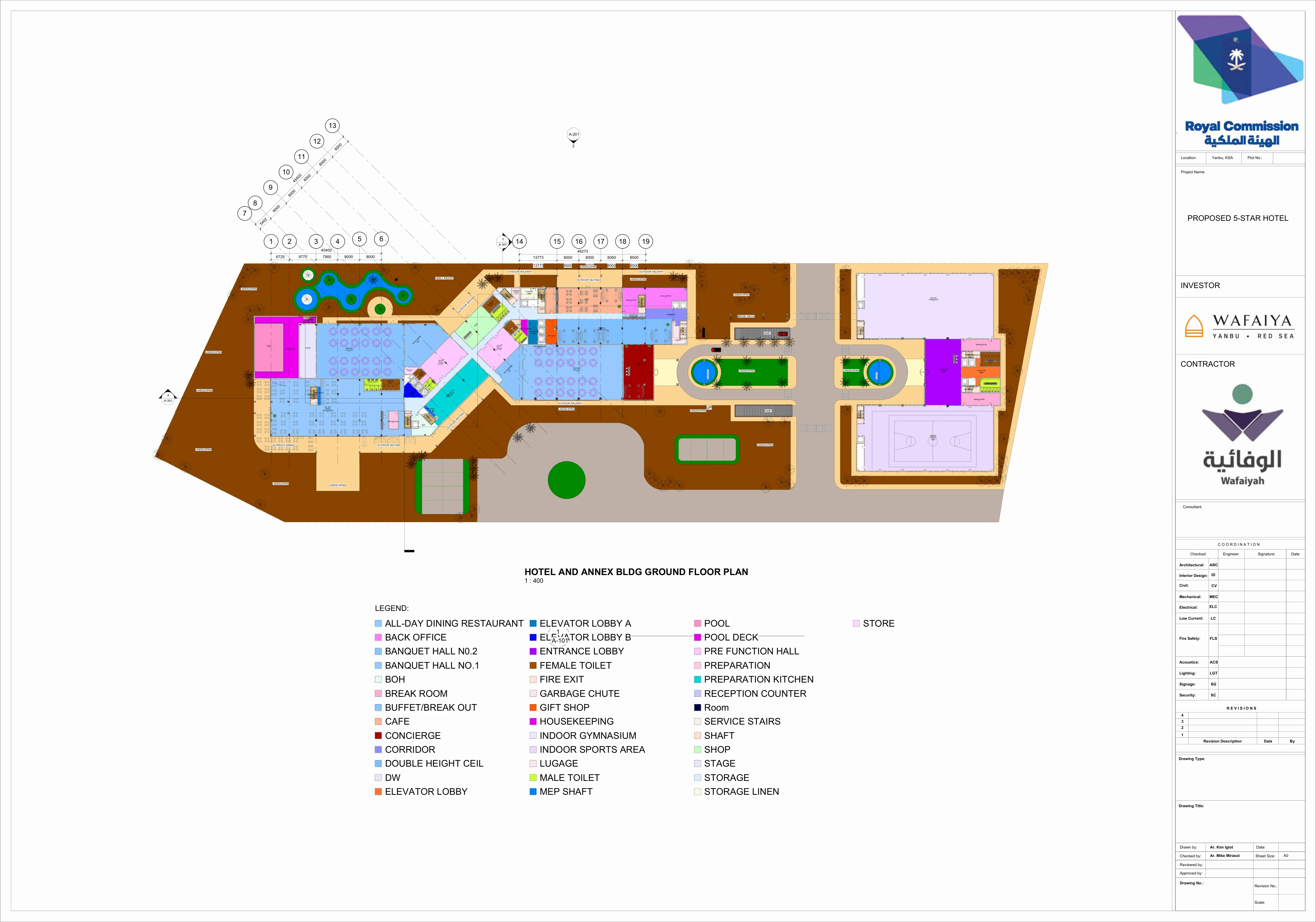
Hotel 5,568.97 m² · Annex 3,020.00 m² scheduled area
Concierge, reception, cafe, banquet halls, all-day dining, preparation and support.
Pool, family-resort area, alfresco dining, walkways and landscaped edges extend the public rooms.
Two large sports/gymnasium-tagged halls flank the annex entrance lobby. Event adaptation is subject to coordination.
Plans & architecture
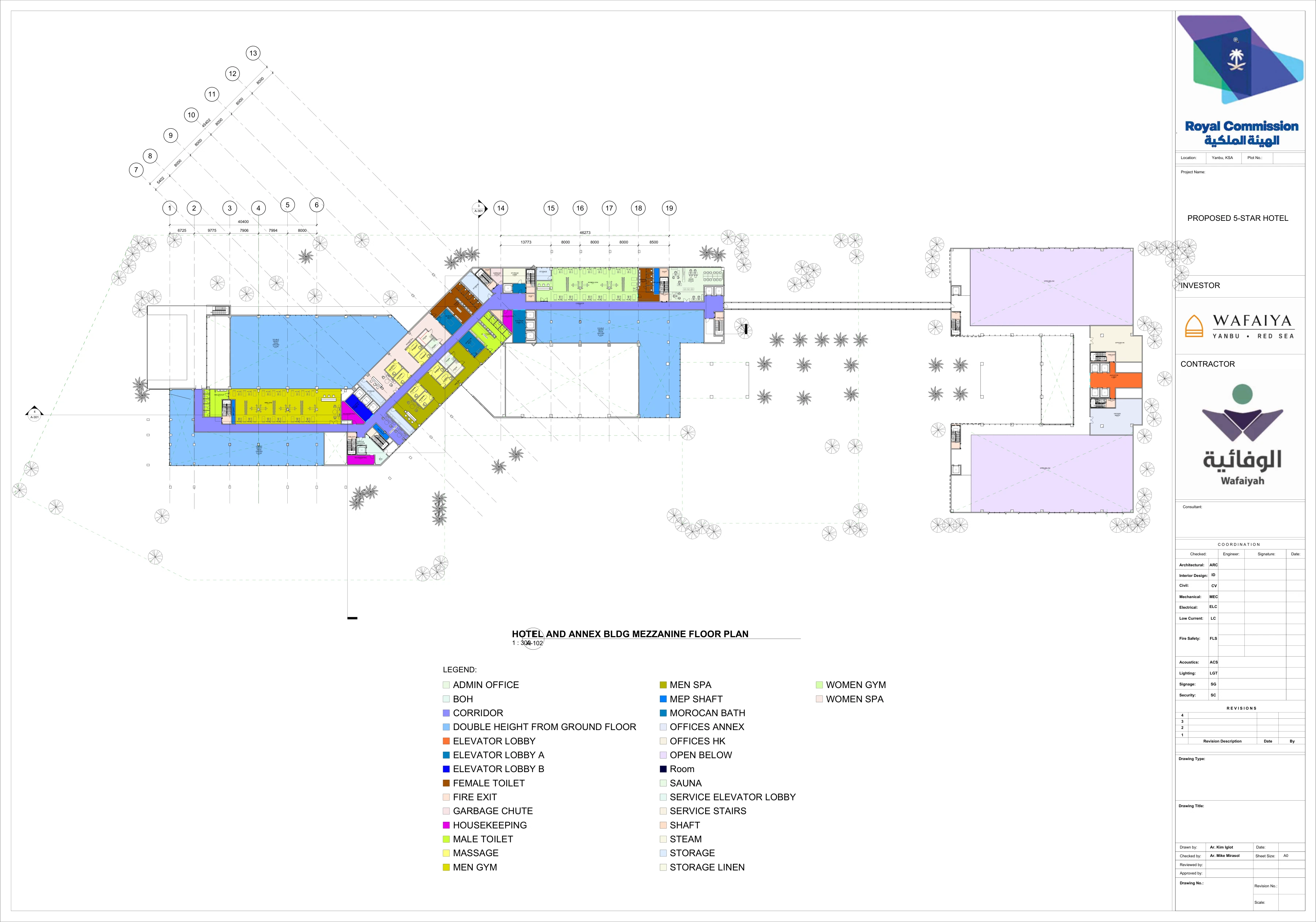
Hotel 2,471.25 m² · Annex 805.00 m² scheduled area
Men’s gym 283 m²; women’s gym 242 m²; men’s spa 156 m²; women’s spa 144 m², plus treatment and wet facilities.
Double-height voids retain the scale of the public rooms below.
Separate wet and dry circulation, coordinate privacy and access, and exclude open-to-below zones from area totals as applicable.
Plans & architecture
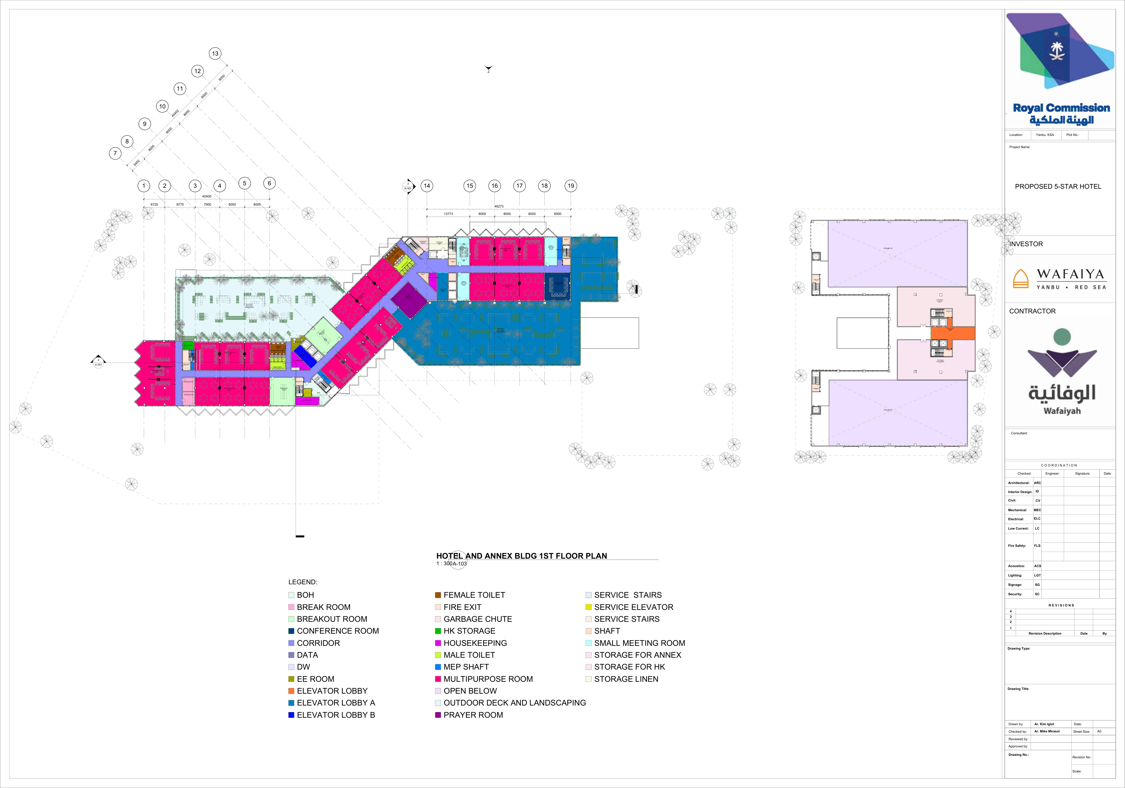
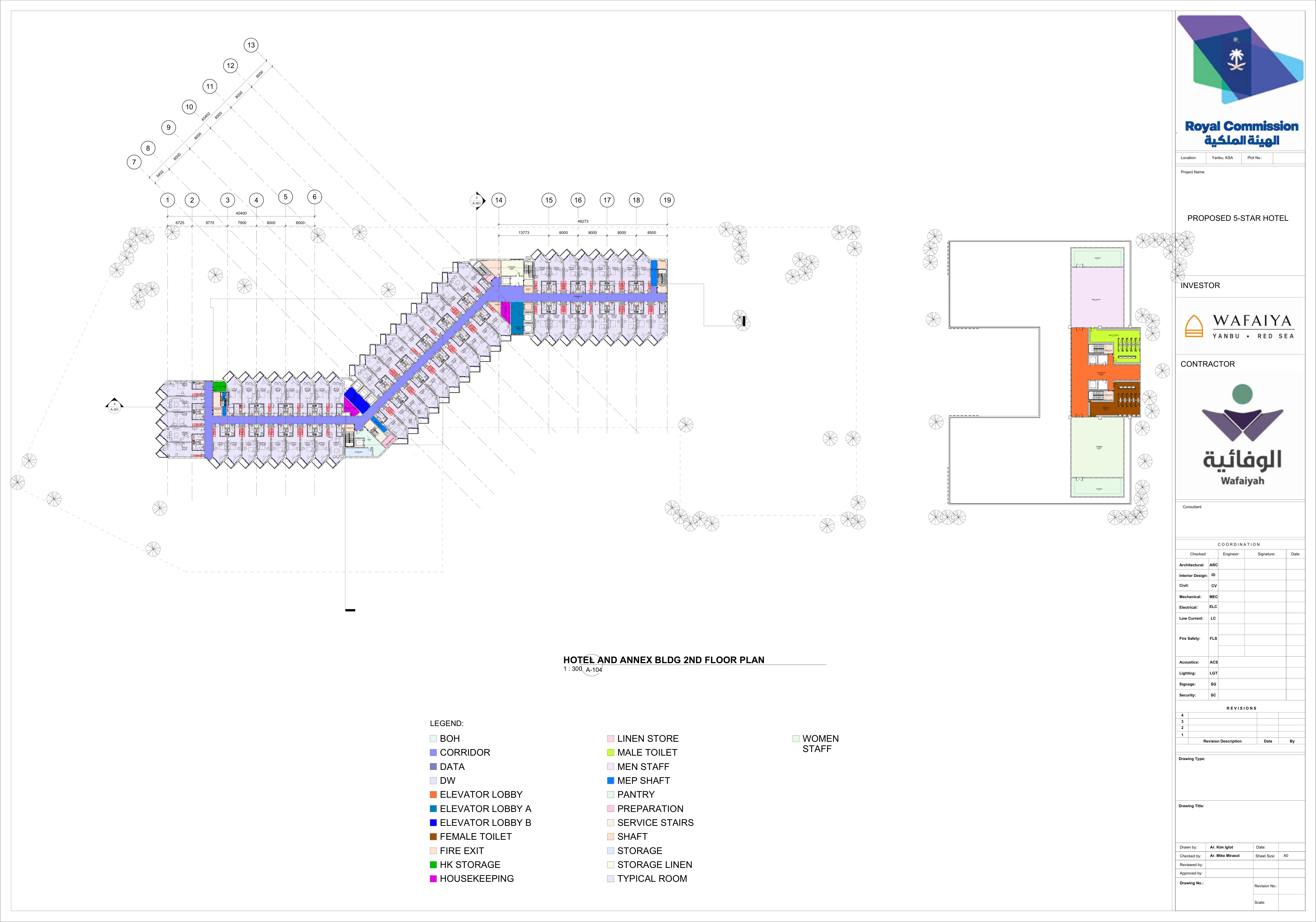
Hotel 3,402.75 m² · Annex 805.00 m² scheduled area
Seven multipurpose-room tags: 213–256 m², totalling 1,578 m² of tagged room area.
Conference, small meeting and breakout rooms, prayer room, housekeeping and linen support.
The older BOQ lists 3,188.64 m² for the main hotel first floor. The presentation uses the supplied tabulation until the gross-area plan is signed off.
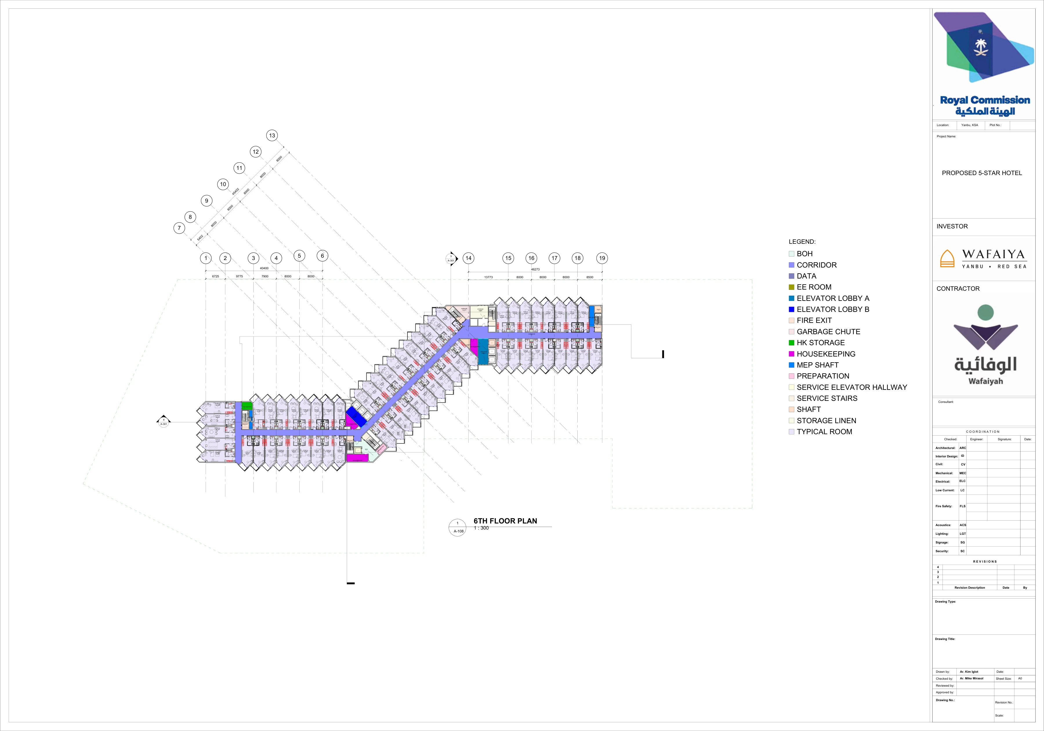
Plans & architecture
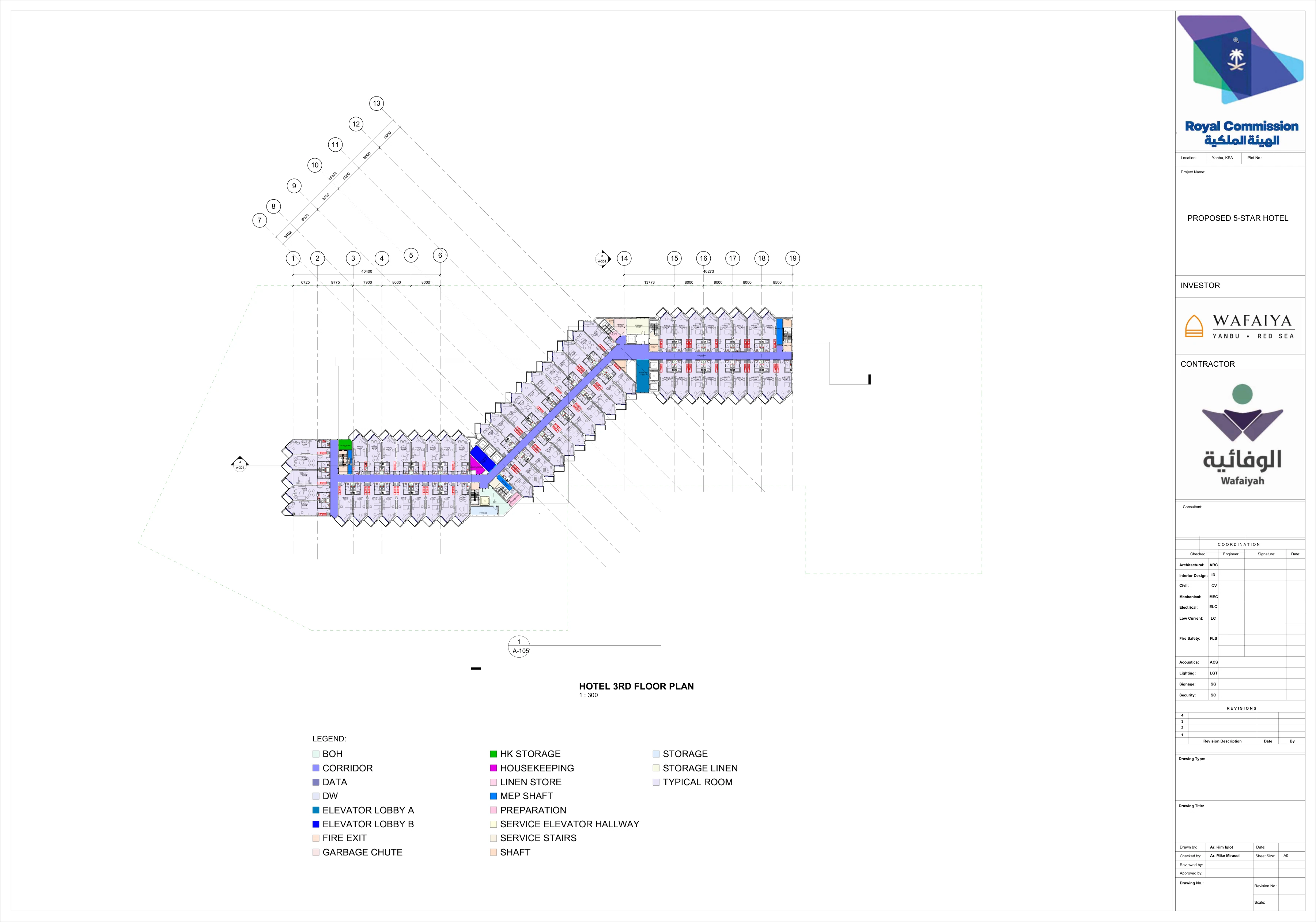
3,402.75 m² hotel scheduled area · 61 modules confirmed
Folded perimeter bays are served by a connected corridor and two principal guest-lift zones.
Housekeeping, linen, service circulation, shafts and escape stairs are retained within the plan.
The supplied floors 2–4 suite mix implies 46 keys per floor if distributed equally. This is a provisional grouping of 61 modules.
Plans & architecture
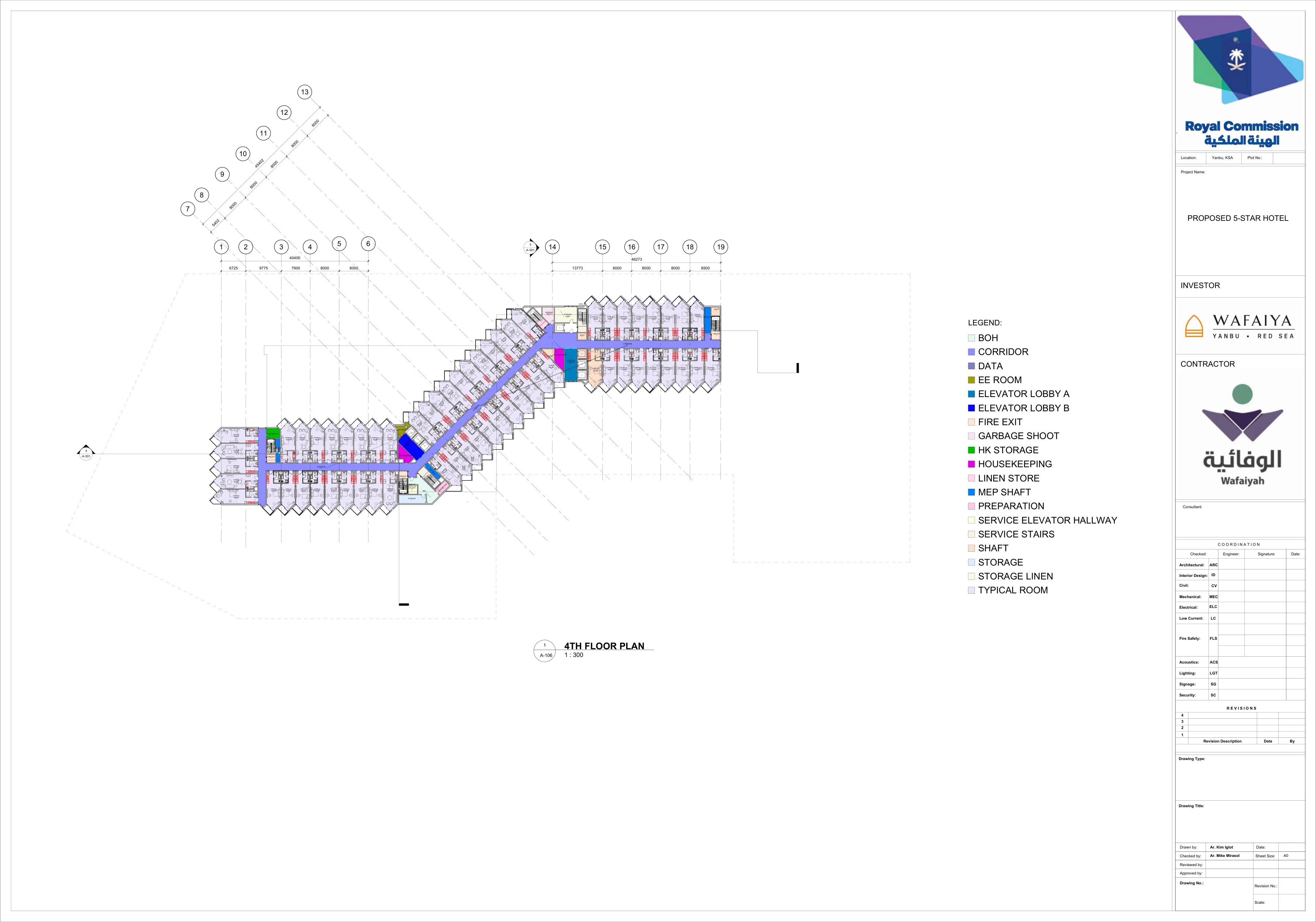
3,402.75 m² hotel scheduled area · 61 modules confirmed
Carry the same room-module geometry, core logic and coordinated facade family through the guest levels.
Record the view from each actual key at this elevation, including the balcony returns and neighbouring wings.
Floors 2–4 form a 183-module group. Final key IDs and suite boundaries must be reconciled with the 138-key arithmetic from the source mix.
Plans & architecture
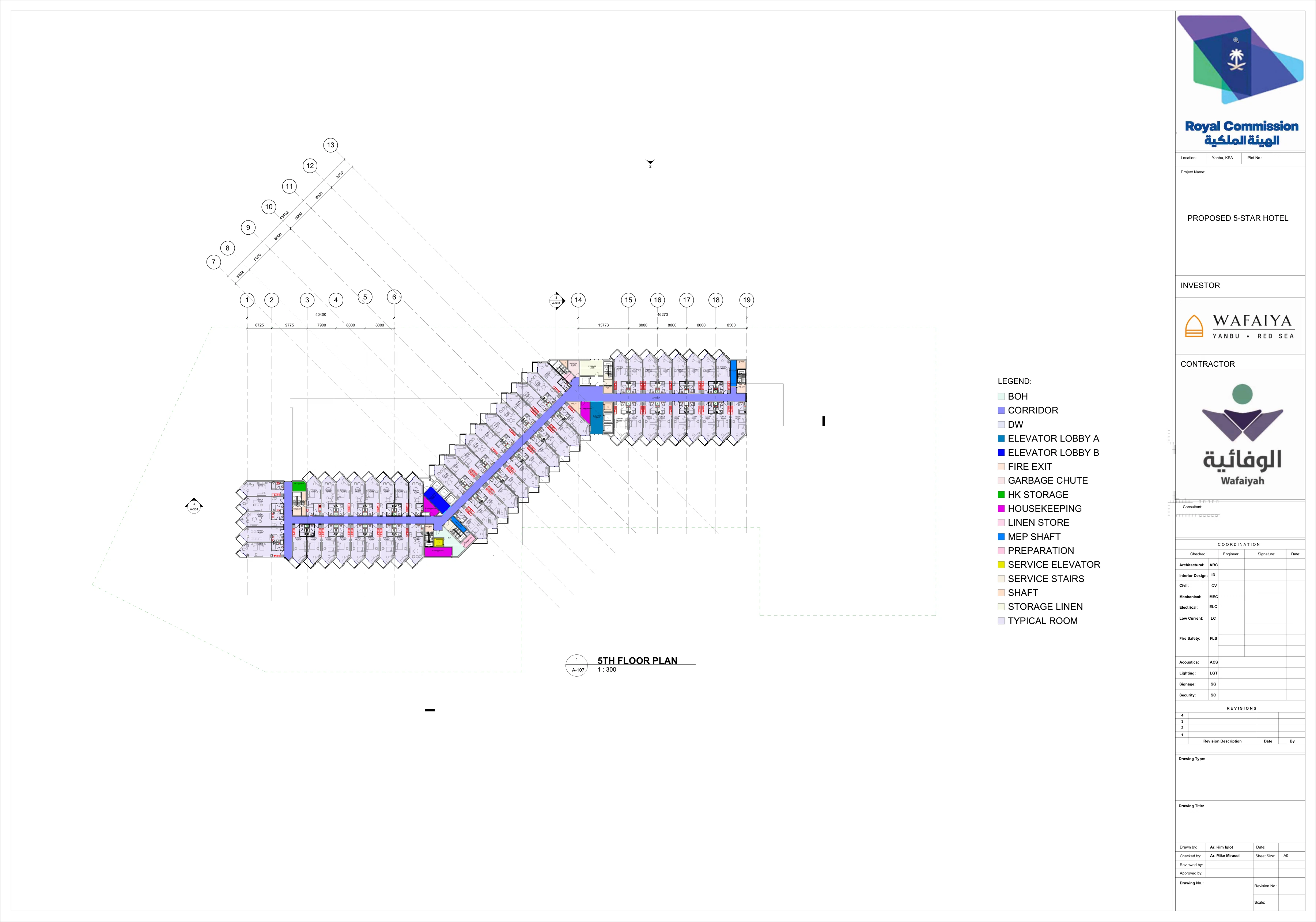
3,402.75 m² hotel scheduled area · 61 modules confirmed
The folded facade remains the organising rhythm for rooms, windows, balconies and shading.
Check privacy, glare and daylight by orientation; do not infer performance solely from the repeated plan.
The client confirms 61 modules per floor. Clean and reconcile room tags and schedules before the statutory issue.
Plans & architecture
3,402.75 m² hotel scheduled area · 61 modules confirmed
The source introduces presidential suites within the combined floors 5–6 matrix.
122 modules across the two upper guest floors can form the listed 90-key provisional mix; this averages 45 keys per floor.
Map each suite to real module IDs and confirm connecting arrangements, fire separation, services and views.
Plans & architecture
3,402.75 m² hotel scheduled area · 61 modules confirmed
The elevation offers a different horizon relationship; views remain subject to the actual room position and surrounding context.
Review roof acoustics, waterproofing, mechanical plant and service routing above guestrooms.
The second through sixth floors total 5 × 61 = 305 room modules. This is the confirmed planning capacity.
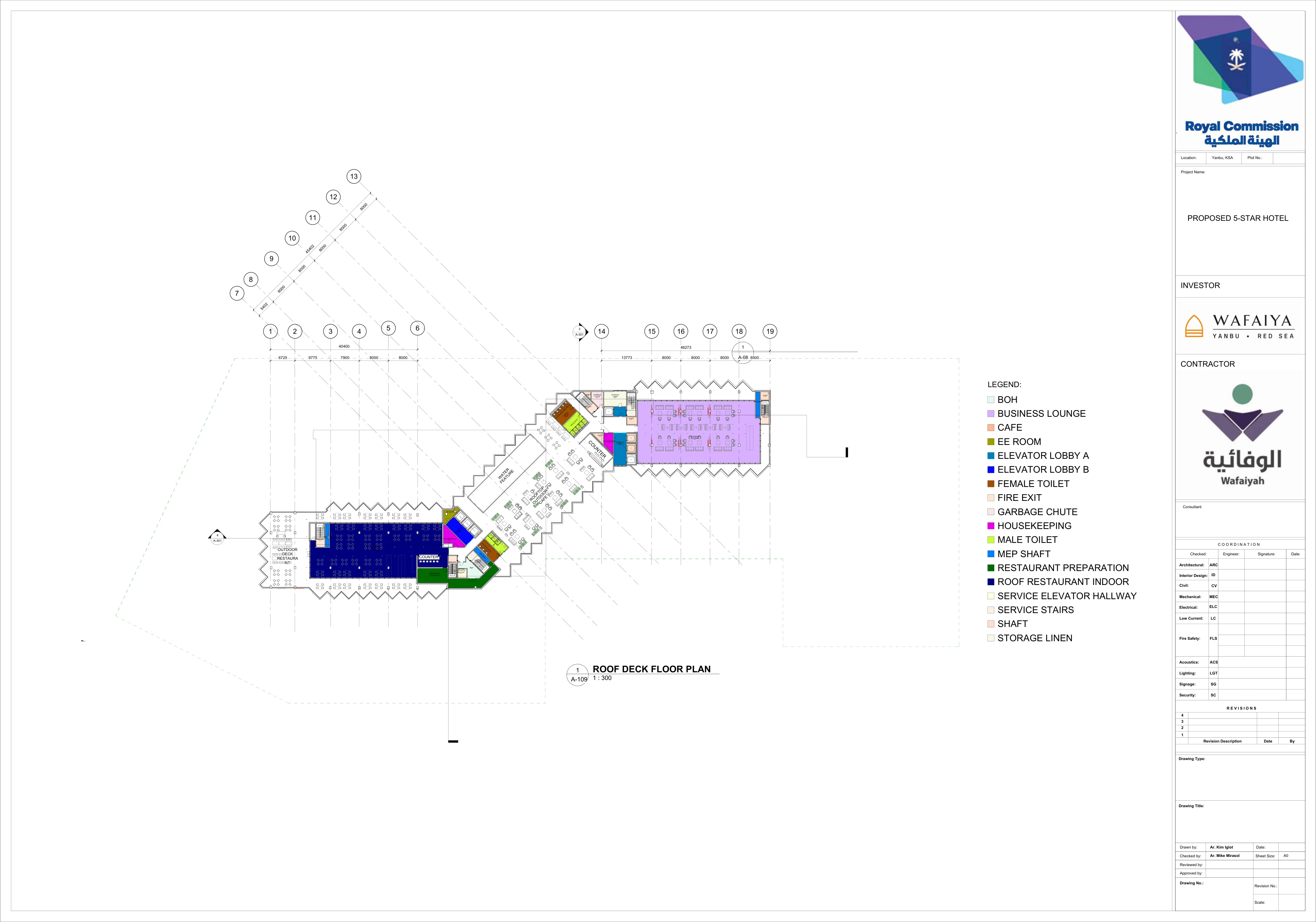
Plans & architecture
Hotel 1,700.00 m² · Annex 1,510.00 m² in supplied tabulation
Indoor restaurant, business lounge, preparation, outdoor restaurant/deck and cafe areas.
Coordinate wind screens, overhead shade, low-sun protection and inboard seating with the latest Forma model.
The sheet also carries an annex 1,557 m² annotation; the BOQ has different roof information. Confirm enclosed areas, open terraces, plant and PV extents.
Plans & architecture
Read the facade rhythm, podium, guest floors and roof treatment as one composition.
Plans & architecture
The return elevations explain the relationship between folded bays, solid walls and the site.
Plans & architecture
Public-room heights, vertical circulation and the guest-floor stack connect the design intent to the building section.
Exterior collection
Exterior collection · 01–04 of 16
Exterior collection
Exterior collection · 05–08 of 16
Exterior collection
Exterior collection · 09–12 of 16
Exterior collection
Exterior collection · 13–16 of 16
Interior collection
Coordinated interiors · spaces 1–2 of 22 · two views of each space
Interior collection
Coordinated interiors · spaces 3–4 of 22 · two views of each space
Interior collection
Coordinated interiors · spaces 5–6 of 22 · two views of each space
Interior collection
Coordinated interiors · spaces 7–8 of 22 · two views of each space
Interior collection
Coordinated interiors · spaces 9–10 of 22 · two views of each space
Interior collection
Coordinated interiors · spaces 11–12 of 22 · two views of each space
Interior collection
Coordinated interiors · spaces 13–14 of 22 · two views of each space
Interior collection
Coordinated interiors · spaces 15–16 of 22 · two views of each space
Interior collection
Coordinated interiors · spaces 17–18 of 22 · two views of each space
Interior collection
Coordinated interiors · spaces 19–20 of 22 · two views of each space
Interior collection
Coordinated interiors · spaces 21–22 of 22 · two views of each space
Submission & evidence
Keep the technical commitments visible and connect each to the drawing or schedule that will close it.
| Workstream | Evidence available | Next coordinated deliverable |
|---|---|---|
| HVAC and plant | Architectural shafts and some service spaces are shown. | Issue system selection, plant layout, intake/exhaust routes, acoustic treatment and maintainable architectural screening. |
| Electrical infrastructure | Electrical-room and shaft tags appear in the architectural plans. | Confirm transformer/substation location, utility access, ventilation and coordinated approvals. |
| Fire and emergency access | Escape stairs and fire-exit labels are shown. | Complete occupancy, travel-distance, stair/exit capacity, fire access, hydrant and fire-water layouts. |
| Waste, loading and kitchens | Basement kitchen, laundry, support and waste-chute tags are shown. | Confirm collection/holding rooms, loading route, clean/dirty separation and event servicing. |
| Accessibility and lifts | Lifts and accessible room quantities appear in the project information. | Complete step-free routes, accessible parking/toilets/rooms, door clearances and lift-traffic analysis. |
| Guestroom and public-space fit-out | Concept interiors and room/floor finish schedules are supplied. | Resolve unplaced/redundant room entries and complete performance specifications, finishes and coordinated room data. |
Submission & evidence
Cross-reference to the 27 items in the supplied RCJY presentation checklist.
| Item | Requirement / evidence link | Presentation coverage | Remaining evidence |
|---|---|---|---|
| 01 | Project identity | Shown / confirm | Project and location included; confirm legal owner, plot details and design-office identity. |
| 02 | Comparable-project identity | Conditional | Checklist reference imagery is included; project names, source attributions and relevance need confirmation. |
| 03 | Areas and functions | Shown / reconcile | Floor tabulation, area definitions and programme included; signed area plans required. |
| 04 | Architectural / visual identity | Shown / develop | Warm stone, bronze screens and repeated folds explained; confirm RCJY identity acceptance. |
| 05 | Concept to final solution | Shown | Z-shaped massing and sawtooth room frontage linked to views and privacy intent. |
| 06 | Urban context | Shown / verify | Supplied contextual views included; align verified survey and neighbouring development. |
| 07 | Circulation and functions | Shown / develop | Arrivals, annex and service logic explained; coordinated movement overlay still required. |
| 08 | Sun and wind studies | Shown / reconcile | Forma evidence included; location, true north and analysis settings must be aligned. |
| 09 | Sustainability and energy | Shown / develop | Envelope, materials, water and PV strategy presented; quantified evidence pending. |
| 10 | Site access, parking, services | Shown / verify | Ground and basement plans included; parking and service locations need reconciliation. |
| 11 | Open-space layouts | Shown | Coloured landscape plan, outdoor connections and planting concept included. |
| 12 | All floor plans, uses and areas | Shown / reconcile | Ten floor-plan sheets included, with area basis and coordination notes. |
| 13 | Vertical sections | Shown | Both building sections included; datum and structural levels need coordination. |
Submission & evidence
Cross-reference to the 27 items in the supplied RCJY presentation checklist.
| Item | Requirement / evidence link | Presentation coverage | Remaining evidence |
|---|---|---|---|
| 14 | Exterior daytime views | Shown | All supplied day views included. |
| 15 | Exterior night views | Shown | Evening waterfront and illuminated arrival views included. |
| 16 | Main interior perspectives | Shown | 44 supplied views across 22 interior spaces included. |
| 17 | Openings, shading, canopies | Shown / develop | Facade and roof shading strategy explained; detail calculations pending. |
| 18 | Exterior and interior materials | Shown / develop | Exterior boards and interior palette included; final product register pending. |
| 19 | Colours and identity | Shown | Stone, bronze, warm timber and restrained teal linked across spaces. |
| 20 | Samples / material boards | Shown | Both original material boards included; physical samples remain a later deliverable. |
| 21 | HVAC and unit locations | Required | No coordinated HVAC system/plant-location drawing supplied. |
| 22 | Architectural AC screening | Required | Provide screened plant elevations, ventilation and maintenance clearances. |
| 23 | Transformer locations | Required | Confirm utility-approved transformer/substation layout. |
| 24 | Waste-container locations | Required | Issue collection, holding and vehicle-access layout. |
| 25 | Fire hydrants | Required | Issue coordinated hydrant, fire-water and emergency-access plan. |
| 26 | Code and RCJY compliance | Required | Provide signed discipline compliance, accessibility and life-safety evidence. |
| 27 | Post-approval programme | Proposed | Indicative sequence supplied for discussion; agreed programme and approvals pending. |
Submission & evidence
A concise close-out path keeps the concept’s strengths intact as the information becomes more detailed.
| Checklist item | Team response recorded | Evidence still to complete |
|---|---|---|
| 1 · Base model / context | Team records verified Google Earth location and true north. | Align survey and Forma coordinates; keep one controlled site model. |
| 2 · Sea-view matrix | Team provides 50/30/20 view allocation. | Issue key-by-key views from bed, seating and balcony, with privacy tests. |
| 3 · Massing comparison | Team explains twin tower, U-form, single tower and Z-form reasoning. | Record comparable yield, facade cost, solar exposure and buildability evidence. |
| 4–6 · Sun, facade and WWR | Team records ongoing BIM study and a full glazed folded face. | Complete annual glare, energy and wing-specific WWR comparisons. |
| 7 · Guestroom validation | Marked “Yes started”; interior design stage noted. | Coordinate prototype king, twin, accessible and complex corner rooms. |
| 8–9 · Operations, lifts and life safety | Planning described as substantially developed. | Issue operator-reviewed BOH routes, lift study and code/egress analysis. |
| 10 · Waterfront experience | Integrated in the design and 3D views. | Retain the sequence while validating shade, wind and accessible movement. |
| 11–12 · Coastal facade and wind | Boards and design consideration recorded. | Complete specifications and tested wind-mitigation details. |
| 13 · Constructability / value | Architectural signature is identified as a priority. | Rationalise folds and components; test the added cost against the room offer. |
Submission & evidence
A clear decision sequence lets the client and reviewing authorities understand what is resolved and what comes next.
Agree site coordinates, true north, floor areas, 305-module schedule, suite groupings, operator brief and annex uses.
Indicative coordination allowance: 4–6 weeks.
Complete the architectural/MEP/fire interfaces, rooms, facade options, wind mitigation and authority review package.
Indicative design/tender allowance: 12–16 weeks; authority review duration to be agreed.
Confirm product evidence, facade and guestroom mock-ups, long-lead items, contractor method and coastal maintenance requirements.
Indicative procurement allowance: 10–16 weeks; some work may overlap design.
Execute the agreed package, test the systems, train operations and complete the required licensing/classification processes.
Initial discussion allowance: 18–24 months; contractor to establish the programme.
Endorse the view-led massing, the 305-module planning capacity, the hotel/annex relationship and the coordinated material direction.
Agree one reconciled area and key schedule, then close the environmental, life-safety, accessibility and building-system evidence.
Issue controlled drawings and schedules with a revision register and signed discipline responsibilities.
Submission & evidence
Reconciliation register for the design team. It keeps the persuasive narrative tied to a traceable evidence base.
| Topic | Source difference | Presentation treatment / next action |
|---|---|---|
| Room capacity | Client confirms 61 modules × 5 guest floors = 305 modules. | Use 305 modules throughout; map the suite groupings to real room/key IDs. |
| Sellable keys | Matrix row quantities total 228 keys; printed subtotals total 220. | Treat 228 as the provisional grouping calculation. The environmental report’s 258-key / 300-room header is an older conflicting reference. |
| Main first-floor area | Supplied tabulation: 3,402.7515 m²; BOQ: 3,188.64 m². | Use supplied tabulation for the presentation total; confirm an issued gross-area plan. |
| Main roof-floor area | Supplied tabulation: 1,700 m²; BOQ: 1,719 m². | Confirm enclosed floor, open terrace and measurement exclusions. |
| Annex roof-floor area | Tabulation/BOQ: 1,510 m²; A-10 annotation: 1,557 m². | Reconcile staff/support area extents and level naming. |
| Combined BUA | This report: 50,456.23 m²; older BOQ cached total: 50,261.11 m². | Difference ≈195.12 m². Do not mix alternate floor inputs. |
| Site coordinates | Checklist: 24.016444° N, 38.161278° E; environmental report: 24.0895° N, 38.0618° E. | Resolve location difference before a new Forma issue or detailed solar sizing. |
| Height / datum | A-13 gives roof deck 32 m and apex 36 m above its ground level; environmental text mentions 34 m. | Reconcile architectural and structural datums and the height used for each analysis. |
| Parking and room tags | Older BOQ records conflicting parking counts; Revit schedules include unplaced/redundant room entries. | Issue cleaned schedules from the coordinated model. Do not use room-object counts as sellable keys. |
Source library
Every supplied PDF sheet is retained: floor plans, elevations, sections, perspectives, solar studies, structural views, schedules and quantities.
Source library
All 21 embedded figures from the supplied environmental report are retained for inspection.
Source library
34 embedded images retained from the supplied workbook, including contextual views and design references.
Source library
17 embedded images retained from the supplied workbook, including contextual views and design references.
Source library
A complete design narrative with direct access to its supporting evidence.
Project plans
31 PDFs in the supplied PDF SHEETS folder; floor-plan file IDs A-01–A-10, elevations A-11–A-12, sections A-13, perspectives A-14–A-17, solar A-18–A-19, structural views A-20–A-23, schedules/BOQ A-24–A-31.
Open drawing library
Project quantities
Screenshot 172400 (area tabulation); Screenshot 172253 (room matrix); ARCHITECTURAL_HOTEL_BOQ.xlsx (cross-check only); client correction confirming 61 × 5 = 305 modules.
Reconciliation and calculation downloads
Project review
RCJY Presentation Requirements Compliance Checklist: 27 items and 34 embedded images. Yanbu Hotel Design Review Checklist v2.1: 13 items, team remarks and 17 embedded images.
RCJY cross-reference · Design review close-out
Design imagery
16 supplied exterior views; 44 supplied interior views in 22 pairs; Coordinated Interiors V2 guide; two material boards; coloured landscape plan.
Exterior collection · Interior collection
Forma evidence
Wafaiya Yanbu — Environmental Analysis, dated 19 September 2026. All 21 embedded figures preserved.
Forma evidence library
Wind analysis methodology
Autodesk describes rapid directional estimates and more detailed CFD-based studies, with activity-specific comfort scales.
Autodesk Forma wind analysis
Regional planting
Regional flora sources document relevant coastal and saline communities; final planting needs a project-specific horticultural assessment.
Northern Tihama flora · Sabkhas flora
Materials and coatings
Product contribution to LEED and coastal coating preparation need evidence for the actual products and assemblies.
USGBC product guidance · QUALICOAT Seaside
Regulatory references
Use the permit edition, project-specific RCJY criteria and hotel-classification criteria accepted by the reviewing authorities.
Saudi Building Code system · Ministry of Tourism published hotel checklist